
 English
 عربى
عربى Español

 English
 عربى
عربى Español
Sodium silicate(HLNAL-1)
Cat:Sodium Silicate Liquid
Sodium silicate (sodium water glass) model HLNAL-1, as follow the national standard GB/T4209-2008 liquid-1 model pr...
See Details
The CO2 curing sodium silicate process is a chemical hardening method in which carbon dioxide gas is introduced to a sodium silicate binder system. The gas reacts with the alkaline silicate solution and converts it into a solid silica gel network that locks aggregate particles into place. Industrial plants use the technique in foundry core and mold production, refractory component shaping, and composite material forming because it delivers fast cycle times with simple equipment and low energy consumption.
Unlike air drying or oven dehydration, CO2 curing does not rely on evaporation alone. The gas participates directly in the chemistry, which is why components can reach handling strength within seconds or minutes instead of hours. This article explains the underlying reaction, the operating parameters that control quality, the required equipment, and the practical measures used to troubleshoot a production line.
Sodium silicate, also known as waterglass, remains liquid until it either loses water or reacts with an acidic species. CO2 curing employs the second path. When carbon dioxide contacts the alkaline surface, it forms carbonic acid, which neutralizes sodium ions and lowers the pH of the binder film. The soluble silicate species then condense into an amorphous silica gel.
Three characteristics distinguish the CO2 route from other hardening methods:
Process users value these features because they enable rapid demolding, dimensionally stable parts, and compatibility with green production standards that restrict organic solvents. The same chemistry applies whether the binder is used at 2 percent in foundry sand, 8 percent in a refractory castable, or 15 percent in a composite board.
The simplified carbonation reaction can be described as sodium silicate plus carbon dioxide producing silica gel plus sodium carbonate. In an industrial binder, commercial sodium silicate is expressed by its molar silica-to-alkali ratio. During gassing, CO2 diffuses through the sand or fiber matrix and dissolves in the water film around each grain.
CO2 dissolves into the aqueous phase and reacts with water to form carbonic acid. The acid gradually consumes the free alkali, and the pH of the binder film drops from roughly 11 to 13 down toward the neutral range.
As pH falls, the ionized silicate species polymerize. Small oligomers grow into a three-dimensional siloxane network that binds aggregate particles at their contact points. This gel carries the initial mechanical strength, although it still contains a significant amount of water.
Sodium ions combine with carbonate to precipitate sodium carbonate. A controlled amount of carbonate contributes to the rigid network, but excessive precipitation means over-gassing. The gel continues to harden for 24 to 72 hours as it dries and densifies.
Every parameter shifts the balance between rapid demolding strength and long-term integrity. The table below summarizes the most important variables observed in production trials.
| Parameter | Typical Range | Effect When Too Low | Effect When Too High |
|---|---|---|---|
| CO2 concentration | 90 to 100 percent | Slow hardening | Surface carbonate crust |
| Gas pressure | 0.1 to 0.4 MPa | Shallow penetration | Cracking and channeling |
| Gassing time | 5 to 60 seconds | Soft core body | Efflorescence and brittleness |
| Binder content | 2 to 5 percent of sand | Low green strength | Poor collapsibility |
| Silicate modulus | 2.2 to 3.2 | Slow reaction, hygroscopic residue | Thick gel, brittle joints |
| Solid content | 35 to 48 percent | Excess water, weak gel | High viscosity, poor mixing |
| Mold temperature | 15 to 35 C | Condensation on surface | Rapid evaporation before reaction |
The interaction between pressure and time deserves special attention. A short high-pressure purge may blow gas through the most permeable zone, leaving dense sections uncured. A lower pressure with a longer dwell time produces a more uniform reaction front. Foundry operators normally calibrate the two values against a standard tensile test specimen before starting a production shift.
A production run follows a repeatable sequence. The exact times vary with part geometry, but the stages remain constant.
Complete gelation does not stop at demolding. In practice, 24 hours of controlled drying can raise tensile strength well above the value measured immediately after gassing.
Installations range from a portable cylinder with a handheld diffuser to a fully automated gassing station with flow control, sealing plates, and exhaust ventilation. The minimum reliable setup includes five components.
Tooling design plays a decisive role. Vents must be distributed so the gas front advances uniformly through every section of the core. Large solid parts require additional vent slots, while thin-walled cores need restrictor plugs to avoid bypass flow. Moisture traps and water separators on the gas line are also recommended because liquid water or oil in the gas stream creates weak zones in the gel.
The starting grade determines how predictable the CO2 response will be. Three properties matter most: the molar silica-to-alkali ratio, the solids content, and the viscosity profile. For a general introduction to the material family, readers can refer to this overview of sodium silicate types and applications.
For foundry sand binders, a modulus between 2.2 and 3.0 gives a fast reaction without making the gel brittle. Higher modulus grades react quickly but produce a dry, stiff film that cracks during demolding. Lower modulus grades cure more slowly and leave a hygroscopic residue that attracts moisture during storage. Solids content, typically in the 35 to 48 percent range, controls how much water the carbonate reaction must displace; excessive water extends gassing time and lowers final strength.
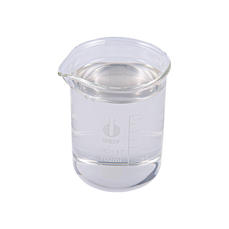 Liquid Sodium Silicate HLNAL-1 for Foundry Sand BindersThis liquid sodium silicate grade suits continuous sand lines by pumping directly into the mixer, avoiding dissolution steps. Its modulus range and solids content align with the binder performance discussed here.View Product →
Plants can choose between liquid and powder forms. Liquid grades are pumped directly into the mixer and require no dissolution step, which suits continuous sand lines. Powder grades simplify warehouse storage and let the operator prepare a solution at a customized solid content on site.
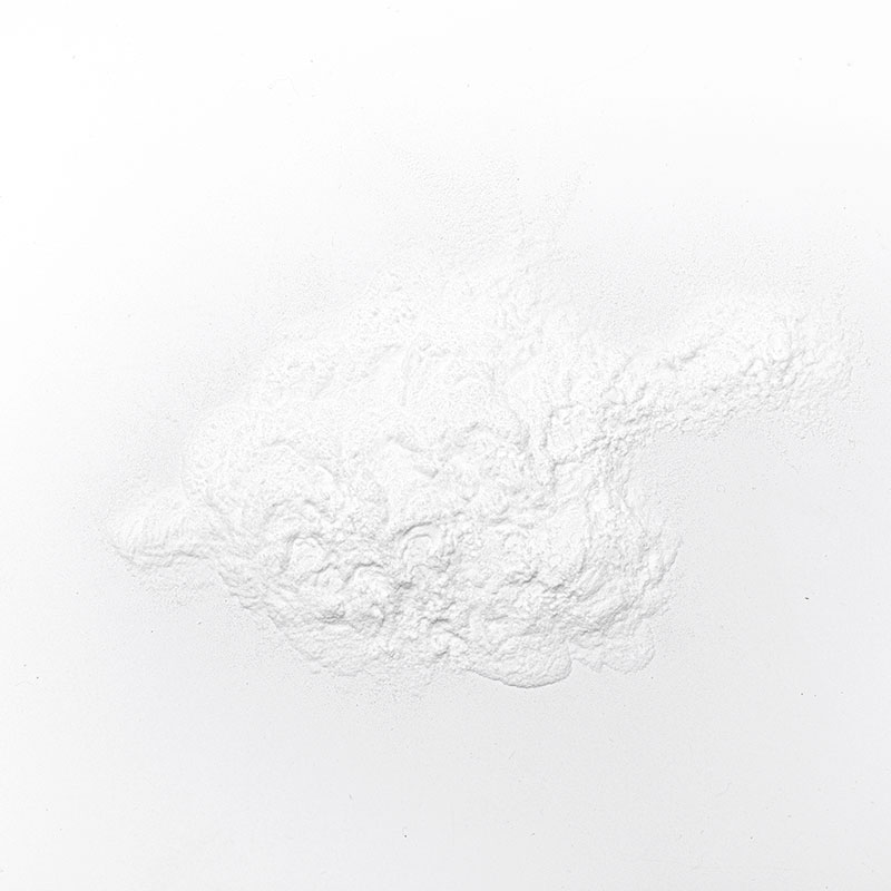 Powdered Sodium Silicate HLNAP-1 for Custom SolutionsThis powder form simplifies warehouse storage and allows on-site preparation at customized solid contents, offering flexibility for plants that prefer batch mixing and reduced liquid handling infrastructure.View Product →
Both routes are used successfully; the decision usually follows plant handling infrastructure and inventory strategy.
The process fits specific niches better than organic binder systems. The table compares its practical profile without reference to trade names.
| Aspect | Advantage | Limitation |
|---|---|---|
| Hardening speed | Handling strength in seconds | Full strength develops over days |
| Emissions | No solvents or combustion fumes | CO2 exposure risk in confined spaces |
| Cost | Low binder addition and no heat | Gas consumption adds recurring cost |
| Storage | Binder solution stable for months | Cured cores reabsorb moisture |
| Demolding | Rapid cycle improves throughput | Poor collapsibility in dense castings |
| Strength | High hot strength for molds | Brittle at high strength levels |
The moisture sensitivity of the cured gel is the most common source of field failures. A core that reaches full tensile strength in dry air can lose a significant portion of that strength after a humid night. Coating the core surface with a moisture barrier, or adjusting the silicate modulus to a slightly higher value, is the usual countermeasure.
The process is not limited to sand casting. Its combination of inorganic chemistry, rapid setting, and fire resistance opens multiple markets.
Each application adjusts the same variables differently. A foundry wants 10-minute handling strength; a refractory producer may accept a longer gassing time in exchange for a denser gel; a composite panel line needs uniform penetration through a planar body. This flexibility is the main reason the process continues to appear in new product development work.
Every metric ton of dry sodium silicate can potentially fix a significant mass of carbon dioxide as sodium carbonate and silica gel. This carbonation pathway is attractive to industries under pressure to lower their net emissions.
Three environmental benefits are commonly reported in technical studies:
The practical carbon balance depends on the gas source. Using waste CO2 from fermentation, ammonia production, or cement kilns gives the largest footprint reduction because the gas would otherwise enter the atmosphere. Operators who can source recovered CO2 at low pressure can combine process economics with a defensible sustainability story.
Consistent part quality depends on monitoring a small set of variables on every shift: gas pressure, gassing time, sand temperature, and binder addition rate. A simple tensile test on standardized specimens performed at the start of each shift detects drift before it creates scrap.
| Symptom | Likely Cause | Corrective Action |
|---|---|---|
| Soft core center | Gas pressure too low or gassing too short | Increase dwell time and verify vent pattern |
| White surface deposit | Over-gassing forming sodium carbonate | Reduce gas flow and check CO2 purity |
| Cracks on demolding | Binder content too high or gel too brittle | Lower binder addition or raise modulus |
| Low strength after storage | Moisture reabsorption by carbonate | Store cores dry and apply sealant if needed |
| Inconsistent penetration | Non-uniform sand density or blocked vents | Rebuild compaction and clean vent holes |
Record the gas pressure and flow rate for each batch, measure the pH of the binder solution weekly, and inspect stored cores for surface moisture. In operations that run more than one shift, the first part of every shift should be a test coupon whose cured strength is compared with the shift target. This practice identifies drifting parameters before they affect production castings.
The gassing step itself typically lasts 5 to 60 seconds depending on part size and gas flow. A core can be demolded within one to two minutes, but the silica gel continues to harden for 24 to 72 hours as residual water evaporates.
Most foundry operations use a modulus between 2.2 and 3.2. A higher modulus reacts faster but produces a more brittle gel, while a lower modulus cures slowly and may leave moisture-attracting residue.
CO2 can be generated on site using a gas generator or recovered from industrial waste streams. Cylinders are the simplest option for small shops, but bulk liquid storage becomes more economical at higher consumption.
The sodium carbonate byproduct absorbs moisture, which softens the gel network and reduces the bond between particles. Dry storage, surface sealants, or a slightly higher silicate modulus helps limit the effect.
Silicate-bonded sand can be mechanically reclaimed and mixed with fresh sand, but the carbonate residue must be controlled. A higher proportion of reclaimed sand usually requires adjusting the binder addition to maintain strength.
The CO2 curing sodium silicate process rewards operators who respect its chemistry. Start with a sodium silicate grade matched to the application, calibrate gas flow and pressure against a standard specimen, and control moisture on the factory floor. The process will then deliver the speed, cost, and environmental benefits that make it an attractive alternative to organic binder systems.
The method continues to expand beyond foundry sand because every improvement in gas distribution and gel control makes it more reliable. Companies evaluating the process should run a small parameter study before full deployment, because local sand, water quality, and ambient humidity all change the optimum settings. With disciplined control, the CO2 curing route offers one of the most practical combinations of rapid hardening and low-carbon operation available in industrial materials processing.
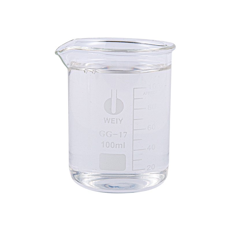
Sodium silicate (sodium water glass) model HLNAL-1, as follow the national standard GB/T4209-2008 liquid-1 model pr...
See Details
Powdered sodium silicate (model HLNAP-2 modulus 2.4±0.1) is a product made of liquid water glass by drying and spra...
See Details
Liquid potassium silicate, model HLKL-4 (modulus 3.6-3.8), potassium silicate solution has better appearance and tr...
See Details
Liquid Potassium Silicate, Model HLKL-5 (Modulus 4.8-5.0), this product is a customized product with ultra-high mod...
See Details
Powdered Potassium Silicate (Model HLKP-1 Mode 2.4±0.1) is a product made of liquid potassium silicate by drying an...
See Details
Powdered Potassium Silicate (Model HLKP-2 Modulus 3.3±0.1) is a product made of liquid potassium silicate by drying...
See Details
Products
Sodium Silicate Potassium Silicate Lithium Silicate Sodium Methylsilicate Potassium Methylsilicate Silica Sol Inorganic Coatings And Binders Flooring SystemContact
Add:No. 7 Jiaye Road, Tongxiang City, Zhejiang Province, China Phone:+86-15257095913 Tel: +86-0573-88980238 Mob: +86-0573-88980238 E-mail:[email protected]